Subscribe to our newsletter to receive monthly specials, manufacturer's feature, and electronics news via email.
See Our latest release of SRI-Newsletter here
View Our List of Archived Newsletter Articles
SRI Links
Visit our Sister Site, Distributor of Industrial Products
Web Search .. Powered by;
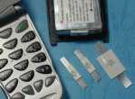
Frontline FSR Series
Application : Rechargeable battery packs
Lithium cell and battery packs
Product Features : Low profile, Solid state
Operation current: 1.2A~4.2 A
Maximum voltage: 15V & 30V
Temperature range: -40ºC to 85ºC
Agency Approvals: UL(E211981), C-UL(Pending), & TÜV(R3-50004084)
Electrical
Characteristics(23ºC)
PartNumber
Fig
Hold Current
Trip Current
Maximum Current
Rated Voltage
Typical Power
Resistance Tolerance
RMIN
R1MAX
IH,A
IT,A
IMAX,A
VMAX,V
Pd,
W
Ω
Ω
FSR120
1
1.2
2.7
15
100
1.2
0.085
0.220
FSR120S
2
1.2
2.7
15
100
1.2
0.085
0.220
FSR175
1
1.75
3.8
15
100
1.5
0.050
0.120
FSR175S
2
1.75
3.8
15
100
1.5
0.050
0.120
FSR200
1
2.0
4.4
30
100
1.9
0.030
0.100
FSR350
1
3.5
6.3
30
100
2.5
0.017
0.050
FSR420
1
4.2
7.6
30
100
2.9
0.012
0.040
IH=Hold current-maximum current at which the device will not trip at 23ºC still air.
IT=Trip current-minimum current at which the device will always trip at 23ºC still air.
V MAX=Maximum voltage device can withstand without damage at its rated current.
I MAX= Maximum fault current device can withstand without damage at rated voltage (V MAX).
Pd=Typical power dissipated from device when in the tripped state in 23ºC still air environment.
RMIN=Minimum device resistance at 23ºC.
R1MAX=Maximum device resistance at 23ºC 1 hour after tripping .
Physical specifications: Lead material:0.13mm nominal thickness,quarter-hard nickel.
Insulating material:Polyester tape.