|

Product Links
|
|
Inside SRI
|
| SRI-Newsletter |
 |
Subscribe to our newsletter to receive monthly specials, manufacturer's feature, and electronics news via email. |
|
 |
|
See Our latest release of SRI-Newsletter here
|
|
View Our List of Archived Newsletter Articles
|
|

SRI Links
|
|
Visit our Sister Site,

Distributor of
Industrial Products
| |
|
Web Search ..
Powered by;

|
|
 |
|
 |
|
|
|
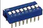
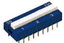
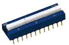
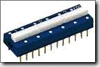
| FDG/FDS Series |
SLIDE TYPE
|
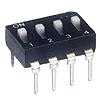 |
Features
Tactile response is performed directly by larger contact pressure to ensure very stable contact.
All UL 94V-0 fire retardant plastics used.
Bottom epoxy sealed standard to ensure free of flux immersion during wave soldering.
Contact wiping on make and break.
Gold plated or silver plated contact to ensure low contact resistance and long operation life.
Ideal for data processing, communications, remote controls and burglar alarm system use, where manual programming is required.
|
Electrical Characteristics
| Contact Rating |
|
| Switching |
25mA, 24VDC |
| Non-switching |
100mA, 50VDC |
| Contact Resistance |
|
| Initial |
50m ohm MAX. |
| After life test |
100m ohm MAX. |
| Insulation Resistance |
1,000M ohm MIN. at 100VDC |
| Dielectric strength |
500VDC for 1 minute |
| Capacitance between adjacent switches 5pF Max. |
Mechanical and Environmental Characteristics
| Temperature Rating |
|
| Operating |
-25oC to +70oC |
| Storage |
-40oC to +85oC |
| Operating Force |
800g Max. |
| Operating Life |
3,000 Operations. |
| Humidity |
95% RH, 40oC for 96 Hrs. |
| Vibration |
Per MIL-STD-202F, Method 204D |
| Solderability |
After flux 230 ± 5oC for
5 ± 0.5 second 95% coverage. |
| Soldering Heat |
After 260 ± 5oC for 5 ± 1 second. |
Dimensions, Construction & Circuitry

SPST
| Positions | 2 | 3 | 4 | 5 | 6 | 7 | 8 | 9 | 10 | 12 |
| A |
6.7
(0.264) |
9.2
(0.362) |
11.7
(0.461) |
14.2
(0.559) |
16.7
(0.657) |
19.2
(0.756) |
21.7
(0.854) |
24.2
(0.953) |
26.7
(1.05) |
31.8
(1.25) |
Unit: mm (inch)
DPST
| Positions | 1 | 2 | 3 | 4 | 5 | 6 |
| A |
6.7
(0.264) |
11.7
(0.461) |
16.7
(0.657) |
21.7
(0.854) |
26.7
(1.05) |
31.8
(1.25) |
Unit: mm (inch)
3PST

| Positions | 1 | 2 | 3 | 4 |
| A |
9.2
(0.362) |
16.7
(0.657) |
24.2
(0.953) |
31.8
(1.25) |
Unit: mm (inch)
4PST
| Positions | 1 | 2 | 3 |
| A |
11.7
(0.461) |
21.7
(0.854) |
31.8
(1.25) |
Unit: mm (inch)

DPDT
| Positions | 1 | 2 | 3 |
| A |
11.7
(0.461) |
21.7
(0.854) |
31.8
(1.25) |
Unit: mm (inch)
Part Numbering System:
|
**Specifications subject to changes**
[Go to Search] [Back]
|
|
|
|