|

Product Links
|
|
Inside SRI
|
| SRI-Newsletter |
 |
Subscribe to our newsletter to receive monthly specials, manufacturer's feature, and electronics news via email. |
|
 |
|
See Our latest release of SRI-Newsletter here
|
|
View Our List of Archived Newsletter Articles
|
|

SRI Links
|
|
Visit our Sister Site,

Distributor of
Industrial Products
| |
|
Web Search ..
Powered by;

|
|
 |
|
|
|
|
|
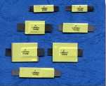 |
Application :
Rechargeable battery packs
Lithium cell and battery packs
Product Features : Low profile, Solid state
Operation current: 1.9A~7.3 A
Maximum voltage: 15V&20V
Temperature range: -40ºC to 85ºC
Agency Approvals: UL (E211981), C-UL(E211981) TÜV pending
|
|
Electrical
Characteristics(23ºC)
|
PartNumber |
Hold
Current |
Trip
Current |
Rated
Voltage |
Maximum
Current |
Typical
Power |
Resistance Tolerance |
|
RMIN |
R1MAX |
|
IH,A |
IT,A |
IMAX,A |
VMAX,V |
Pd,
W |
Ω |
Ω |
|
FLR190 |
1.9 |
3.9 |
15 |
100 |
1.2 |
0.039 |
0.102 |
|
FLR190S |
1.9 |
3.9 |
15 |
100 |
1.2 |
0.039 |
0.102 |
|
FLR260 |
2.6 |
5.8 |
15 |
100 |
2.5 |
0.020 |
0.063 |
|
FLR260S |
2.6 |
5.8 |
15 |
100 |
2.5 |
0.020 |
0.063 |
|
FLR380 |
3.8 |
8.3 |
15 |
100 |
2.5 |
0.013 |
0.037 |
|
FLR450 |
4.5 |
8.3 |
20 |
100 |
2.5 |
0.011 |
0.028 |
|
FLR550 |
5.5 |
10.5 |
20 |
100 |
2.8 |
>0.009 |
0.022 |
|
FLR600 |
6.0 |
11.7 |
20 |
100 |
2.8 |
0.007 |
0.019 |
|
FLR730 |
7.3 |
14.1 |
20 |
100 |
3.3 |
0.006 |
0.015 |
IH=Hold current-maximum current at which the device will not trip at 23ºC still air.
IT=Trip current-minimum current at which the device will always trip at 23ºC still air.
V MAX=Maximum voltage device can withstand without damage at its rated current.
I MAX= Maximum fault current device can withstand without damage at rated voltage (V MAX).
Pd=Typical power dissipated from device when in the tripped state in 23ºC still air environment.
RMIN=Minimum device resistance at 23ºC.
R1MAX=Maximum device resistance at 23ºC 1 hour after tripping .
Physical specifications:
Lead material:0.13mm nominal thickness,quarter-hard nickel.
Insulating material:Polyester tape. |
|
FLR Product Dimensions (Millimeters)
|
|
PartNumber |
Fig |
A
|
B
|
C
|
D
|
F |
|
Min |
Max |
Min |
Max |
Min |
Max |
Min |
Max |
Min |
Max |
|
FLR190 |
1 |
19.9
|
22.1
|
4.9
|
5.5
|
0.6
|
1.0
|
5.5
|
7.5
|
3.9
|
4.1
|
|
FLR190S |
2 |
19.9 |
22.1 |
4.9
|
5.5
|
0.6
|
1.0
|
5.5
|
7.5
|
3.9
|
4.1
|
|
FLR260 |
1 |
20.9
|
23.1
|
4.9
|
5.5
|
0.6
|
1.0
|
4.1
|
5.5
|
3.9
|
4.1
|
|
FLR260S |
2 |
20.9
|
23.1
|
4.9
|
5.5
|
0.6
|
1.0
|
4.1
|
5.5
|
3.9
|
4.1
|
|
FLR380 |
1 |
24.0
|
26.0
|
6.9
|
7.5
|
0.6
|
1.0
|
4.1
|
5.5
|
4.9
|
5.1
|
|
FLR450 |
1 |
24.0
|
26.0
|
9.9
|
10.5
|
0.6
|
1.0
|
5.3
|
6.7
|
5.9
|
6.1
|
|
FLR550 |
1 |
35.0
|
37.0
|
6.9
|
7.5
|
0.6
|
1.0
|
5.3
|
6.7
|
4.9
|
5.1
|
|
FLR600 |
1 |
24.0
|
26.0
|
13.9
|
14.5
|
0.6
|
1.0
|
4.1
|
5.5
|
5.9
|
6.1
|
|
FLR730 |
1 |
27.1
|
29.1
|
13.9
|
14.5
|
0.6
|
1.0
|
4.1
|
5.5
|
5.9
|
6.1
|
|
Thermal Derating
Curve
 |
|
Typical Time-To-Trip at 23ºC
|
A =FLR190/FLR190S |
B =FLR260/FLR260S |
| C =FLR380 |
D =FLR450 |
| E =FLR550 |
F =FLR600 |
| G =FLR730 |
| | |
|
**Specifications subject to changes**
[Go to Search] [Back]
|
|
|