|

Product Links
|
|
Inside SRI
|
| SRI-Newsletter |
 |
Subscribe to our newsletter to receive monthly specials, manufacturer's feature, and electronics news via email. |
|
 |
|
See Our latest release of SRI-Newsletter here
|
|
View Our List of Archived Newsletter Articles
|
|

SRI Links
|
|
Visit our Sister Site,

Distributor of
Industrial Products
| |
|
Web Search ..
Powered by;

|
|
 |
|
|
|
|
|
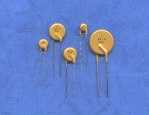 |
Application :
Wide variety of electronic equipment
Product Features : Low hold current, Solid state
Radial-leaded product ideal for up to 120V/120AC
Operation current: 100mA~3.75A
Maximum voltage: 120V
Temperature range: -40ºC to 85ºC
Agency Approvals: UL, C-UL & TÜV pending
|
|
Electrical
Characteristics(23ºC)
|
PartNumber |
Hold
Current |
Trip
Current |
Max.Time
to Trip |
Rated
Voltage |
Maximum
Current |
Typical
Power |
Resistance Tolerance |
|
RMIN |
R1MAX |
|
IH,A |
IT,A |
at 5XIH |
VMAX,V |
IMAX,A |
Pd,
W |
Ω |
Ω |
| FRA010-120 |
0.10 |
0.20 |
4.0 |
40 |
120 |
0.57 |
2.50 |
7.50 |
| FRA017-120 |
0.17 |
0.34 |
3.0 |
40 |
120 |
0.59 |
2.00 |
7.00 |
| FRA020-120 |
0.20 |
0.40 |
2.2 |
40 |
120 |
0.62 |
1.83 |
4.40 |
| FRA025-120 |
0.25 |
0.50 |
2.5 |
40 |
120 |
0.68 |
1.25 |
3.00 |
| FRA030-120 |
0.30 |
0.60 |
3.0 |
40 |
120 |
0.74 |
0.88 |
2.10 |
| FRA040-120 |
0.40 |
0.80 |
3.8 |
40 |
120 |
0.84 |
0.55 |
1.29 |
| FRA050-120 |
0.50 |
1.00 |
4.0 |
40 |
120 |
1.16 |
0.50 |
1.17 |
| FRA065-120 |
0.65 |
1.30 |
5.3 |
40 |
120 |
1.32 |
0.31 |
0.72 |
| FRA075-120 |
0.75 |
1.50 |
6.3 |
40 |
120 |
1.38 |
0.25 |
0.60 |
| FRA090-120 |
0.90 |
1.80 |
7.2 |
40 |
120 |
1.49 |
0.20 |
0.47 |
| FRA110-120 |
1.10 |
2.20 |
8.2 |
40 |
120 |
2.25 |
0.15 |
0.38 |
| FRA135-120 |
1.35 |
2.70 |
9.6 |
40 |
120 |
2.55 |
0.12 |
0.30 |
| FRA160-120 |
1.60 |
3.20 |
11.4 |
40 |
120 |
2.85 |
0.09 |
0.22 |
| FRA185-120 |
1.85 |
3.70 |
12.6 |
40 |
120 |
3.15 |
0.08 |
0.19 |
| FRA250-120 |
2.50 |
5.00 |
15.6 |
40 |
120 |
3.75 |
0.05 |
0.13 |
| FRA300-120 |
3.00 |
6.00 |
19.8 |
40 |
120 |
4.20 |
0.04 |
0.10 |
| FRA375-120 |
3.75 |
7.50 |
24.0 |
40 |
120 |
4.80 |
0.03 |
0.08
|
IH=Hold current-maximum current at which the device will not trip at 23ºC still air.
IT=Trip current-minimum current at which the device will always trip at 23ºC still air.
V MAX=Maximum voltage device can withstand without damage at its rated current.
I MAX= Maximum fault current device can withstand without damage at rated voltage (V MAX).
Pd=Typical power dissipated from device when in the tripped state in 23ºC still air environment.
RMIN=Minimum device resistance at 23ºC.
R1MAX=Maximum device resistance at 23ºC 1 hour after tripping .
Physical specifications:
Lead material: FRA010~FRA090 Tin plated copper,22 AWG.
FRA110~FRA375 Tin plated copper,20 AWG.
Soldering characteristics:MIL-STD-202, Method 208E.
Insulating coating:Flame retardant epoxy ,meet UL-94V-0 requirement. |
|
FRA Product Dimensions (Millimeters)
|
|
FRA
010-120 ~ FRA 090-120
Lead Size :22AWG,
Ø 0.65
mm Diameter |
FRA
110-120 ~ FRA 375-120
Lead Size : 20AWG,
Ø
0.81 mm
Diameter |
|
PartNumber |
A
|
B
|
C
|
D
|
E
|
F |
|
Maximum |
Maximum |
Typical |
Minimum |
Maximum |
Typical |
| FRA010-120 |
7.4 |
12.7 |
5.1 |
7.6 |
4.6 |
2.7 |
| FRA017-120 |
7.4 |
12.7 |
5.1 |
7.6 |
4.6 |
2.7 |
| FRA020-120 |
7.4 |
12.2 |
5.1 |
7.6 |
4.6 |
2.7 |
| FRA025-120 |
7.4 |
12.7 |
5.1 |
7.6 |
4.6 |
2.7 |
| FRA030-120 |
7.4 |
13.0 |
5.1 |
7.6 |
4.6 |
2.7 |
| FRA040-120 |
7.6 |
13.5 |
5.1 |
7.6 |
4.6 |
2.7 |
| FRA050-120 |
7.9 |
13.7 |
5.1 |
7.6 |
4.6 |
2.7 |
| FRA065-120 |
9.7 |
14.5 |
5.1 |
7.6 |
4.6 |
2.7 |
| FRA075-120 |
10.4 |
15.2 |
5.1 |
7.6 |
4.6 |
2.7 |
| FRA090-120 |
11.7 |
15.8 |
5.1 |
7.6 |
4.6 |
2.7 |
| FRA110-120/td>
| 13 |
18.0 |
5.1 |
7.6 |
4.6 |
2.7 |
| FRA135-120/td>
| 14.5 |
19.6 |
5.1 |
7.6 |
4.6 |
2.7 |
| FRA160-120/td>
| 16.3 |
21.3 |
5.1 |
7.6 |
4.6 |
2.7 |
| FRA185-120/td>
| 17.8 |
22.9 |
5.1 |
7.6 |
4.6 |
2.7 |
| FRA250-120/td>
| 21.3 |
26.4 |
10.2 |
7.6 |
4.6 |
2.7 |
| FRA300-120/td>
| 24.9 |
30.0 |
10.2 |
7.6 |
4.6 |
2.7 |
| FRA375-120/td>
| 28.5,/td>
| 33.5 |
10.2 |
7.6 |
4.6 |
2.7
|
|
Thermal Derating
Curve
 |
|
Typical Time-To-Trip at 23ºC
| A =FRA010-120 |
B =FRA017-120 |
C =FRA020-120 |
D =FRA025-120 |
| E =FRA030-120 |
F =FRA040-120 |
G =FRA050-120 |
H =FRA065-120 |
| I =FRA075-120 |
J =FRA090-120 |
K =FRA110-120 |
L =FRA135-120 |
| M =FRA160-120 |
N =FRA185-120 |
O =FRA250-120 |
| P =FRA300-120 |
Q =FRA375-120
|
| | |
|
**Specifications subject to changes**
[Go to Search] [Back]
|
|
|