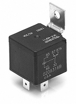
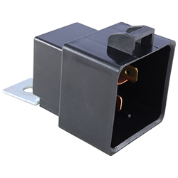
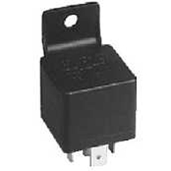
Automotive relays of all shapes and sizes can be found in just about every car, truck, and even boats. Relays in general are used to enable a low amperage circuit to switch on or off a higher amperage circuit, like turning on your headlights. If you were to try and directly hook up your headlights to the headlight switch you would exceed the amperage rating of the switch, melt wires, and risk an electrical fire. Relays are also used to switch multiple things at the same time using one output. A single output connected to multiple relays will allow you to open continuity and/or close continuity simultaneously, for example turning on your radio while the antenna extends. This article will cover some of the parts and characteristics of the automotive relay and some of the considerations taken with there design and use.
Automotive Relay Circuit Design
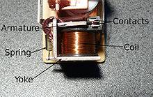
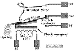
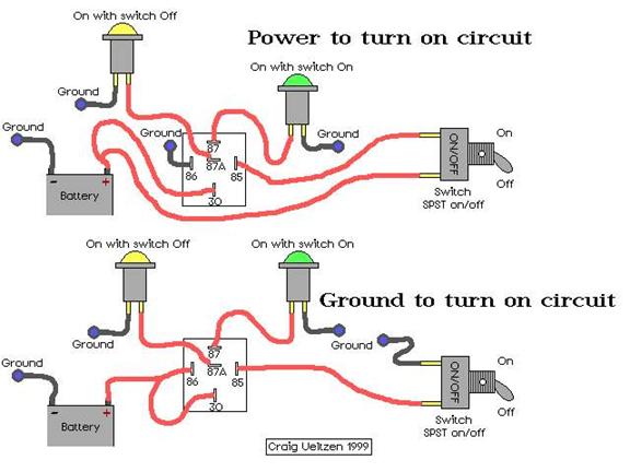
Most automotive relays that you will see are either Single-Pole, Single-Throw (SPST) or Single-Pole, Double-Throw (SPDT) and draw very little current (less than 200 milliamps). They have either normally closed or normally open contacts that will handle up to 30 or 40 amps and operate using a control circuit that has the coil and a load circuit which has the switch. When power is applied to the coil, a magnetic field is created which either opens or closes the switch. The diagrams below illustrate how this works.
(http://en.wikipedia.org/wiki/Relay) (Craig Ueltzan 1999)
The Snubber
Once the power is disconnected from the relay and the magnetic field collapses across the coil, a voltage spike of several hundred volts in the reverse direction of normal current flow occurs. Because automotive relays are often controlled by electronic circuits that are sensitive to voltage spikes, this reverse voltage must be controlled and dissipated. Most commonly either a resistor or a diode is placed across the coil of the automotive relay to do this. The diode or resistor is often referred to as a snubber
Diode Snubbers
As we know from our article about the diode, a reverse biased direction does not allow current to flow through a diode, so when voltage direction is normal, no current flows through the diode, but when this reverse voltage occurs,the diode becomes forward biased and excess voltage is allowed to pass through the completed circuit to the other end of the coil. This current flows around in the diode and coil circuit until the voltage is dissipated.
Resistor Snubbers
Resistor snubbers work by allowing only a certain amount of current to flow though the resistor during a voltage spike. According to allaboutcircuits.com, “Resistor-Capacitor snubbers have been used in automobiles for years on engine ignition systems, minimizing the arcing across the switch contact "points" in the distributor with a small capacitor called a condenser. As any mechanic can tell you, the service life of the distributor's ‘points’ is directly related to how well the condenser is functioning.”
Life Expectancy
Automotive relays will also fail after a time. Some are even rated by the number of times they will close a circuit before burning out (common relays are usually rated to 100,000 operations). Fortunately ISO automotive relays have been standardized, so many manufacturers make the same style relay making them much less expensive to replace than a switch.
http://en.wikipedia.org/wiki/Snubber
http://www.the12volt.com/relays/relays.asp
https://electronicsclub.info/relays.htm
http://www.autoshop101.com/forms/hweb2.pdf
|