We’ve have all used potentiometers in our everyday life from adjusting the volume of the radio to dimming the light level in a room. A potentiometer (or pot) is basically an adjustable resistor. The helical ones we still use today have been around since the 40’s and now have so many varieties and power ratings that it can be difficult to choose the right one. Potentiometers have three terminals: one terminal is connected to a power source, another is hooked up to ground, and the third terminal (the wiper) slides across a strip or coil of resistive material. This article will explain the basics of the potentiometer and examine a few basic types.
How potentiometers work
In order to adjust the resistance of the potentiometer and therefore the current flow, a knob of some sort is used to move the third terminal along the resistive strip. When used to regulate current, the potentiometer is limited by the maximum resistance of the strip. The change in the resistance is either linear, like a dimmer for light, or logarithmic, like volume controls, which is used because the human ear does not respond linearly to loudness - it responds to the logarithm (curve) of loudness. This is accomplished by slowly increasing the speed that the wiper traverses the resistive material.
Potentiometer Types
Ceramic Metal (Cermet)
 These potentiometers use cermet construction in the manufacture of the resistance element. Advantages are high temperature use, wide resistance range, stability, and durability over wire-wound, metal film and carbon units.
Composition, Carbon
 Carbon composition potentiometers use a resistive element consists of carbon particles which are mixed with a binder, molded into a circular shape for the element, and then baked.
Conductive Plastic
 Conductive plastic potentiometers the resistive element consists of a blend of resin and processed carbon powder applied to a plastic or ceramic substrate.
Non-Linear
 As explained earlier, the resistance of these varies non-uniformly along the resistive strip–being greater, or less, for equal slider movement at various points along the resistance element.
Single-Turn
 These potentiometers have a slider travels the complete length of the resistive element with only one revolution of the shaft.
Sliding; Rectilinear
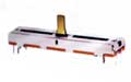 Sliding pots are constructed with the wiper sliding along the resistive element in straight motion rather than circular. Most often the taper is linear and these potentiometers are used to adjust loudness, frequency attenuation, and other characteristics of audio signals.
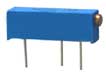
Trimmer
 Trimmers are small potentiometers to permit fine adjustment of resistance values in a circuit during initial calibration or when recalibration is required. They are usually mounted directly on circuit boards, and turned with a small screwdriver or shaft.
Wirewound
 For these, the resistance element is constructed of turns of a wire on which the wiper contacts only a small portion of each turn. They offer good stability, low noise, high power capability, etc.; however, inherent internal capacitance/inductance limit usage at high frequency.
Rheostats
 Rheostats are three-terminal resistors using only two terminals (one side and the sliding wiper with the third terminal connected to wiper). Often rheostats are designed to handle high voltage and control current in place of conventional potentiometers.
Digital potentiometers
 Digital potentiometers, sometimes called digital POT, RDAC, or digipot mimic the characteristics of an analog potentiometer. Digital potentiometers have higher resolutions, better reliability, better stability, faster adjustment, more functions, and better dynamic control. Just about any application that uses a trim pot can use a digital pot. Digital pots are finding wide use in LCD panels for VCOM adjustment and panel contrast/brightness control, programmable power supplies, RF amplifier biasing, and automotive electronics.
Design Considerations
One of the biggest issues when using a digital pot is whether to use it in a true potentiometer (three-terminal) or in a variable resistor (two-terminal) configuration because of the amount of current the wiper can carry may vary in a two-terminal design. Depending on the digital pot, maximum allowable wiper currents range from the hundreds of micro amps to milliamps. The designer must be careful not to exceed the maximum current on these. One solution to this issue is to use the digital potentiometer in a three-terminal configuration when possible and to buffer the wiper with an op amp. This circuit will ensure that the wiper current is equivalent to the input bias current of the op amp. By using an op amp with an input bias current spec in the Pico amps, any errors due to the value or changes in the value of the wiper resistance are virtually eliminated.
What’s new in digital pots?
Recent advances have made it possible to economically fabricate digital pots with 1% end-to-end resistor tolerances. Some recently introduced parts can retain a factory-measured resistor tolerance value in memory. External software can access and use the stored value for compensating for resistance errors when computing wiper settings.
Sources:
http://www.geofex.com/Article_Folders/potsecrets/potscret.htm
http://www.wisegeek.com/what-is-a-potentiometer.htm
http://sound.westhost.com/pots.htm
http://www.analog.com/en/digital-to-analog-converters/digital-potentiometers
/products/faqs/CU_faq_digital_potentiometers/resources/fca.html#1e
http://www.maxim-ic.com/products/digi_pot/
http://electronicdesign.com/Articles/ArticleID/19305/19305.html
http://www2.eem.com/Potentiometers_Trimmers_Controls.aspx