When two objects of different potential touch, a static or electrical shock can occur - ZAP! Electrons are transferred between objects, like when you rub them together, one object becomes more positive and the other more negative, hence changing their potential, and allowing this spark to occur. In general terms, electrical potential is a measurement of how many electrons that can be pushed into an object with a specific amount of pressure - or voltage in this context. In electronic circuit theory, ideally the ground can be thought of as an unlimited black hole that charge can flow into without changing its potential, and electricity prefers to travel where voltage is the lowest, so that is why it will travel to the earth if possible because the earth has the lowest voltage.
 Low impedance at the signal frequency of the electrode-to-earth connection determines its quality, and that quality is improved by increasing the surface area of the electrode in contact with the earth, increasing the depth to which it is driven, using several connected ground rods, increasing the moisture content of the soil, improving the conductive mineral content of the soil, and increasing the land area covered by the ground system.1 Low impedance at the signal frequency of the electrode-to-earth connection determines its quality, and that quality is improved by increasing the surface area of the electrode in contact with the earth, increasing the depth to which it is driven, using several connected ground rods, increasing the moisture content of the soil, improving the conductive mineral content of the soil, and increasing the land area covered by the ground system.1
According to an article in Wikipedia, early telegraphs used the ground to complete the circuit, and during dry weather, the ground connection often developed a high resistance, requiring water to be poured on the ground rod to enable the telegraph to work or phones to ring. A low impedance ground is imperative to both surge protection designs and power quality. A regular check and upgrade (as needed) of grounding systems will reduce interference and line noise, improve power factors, reduce the risk of accidental electrocution, help decrease potentially damaging harmonics and improve the efficiency and durability of surge protection equipment.5
Earth resistance is measured in two ways for two important fields of use:
1. Determining effectiveness of "ground" grids and connections that are used with electrical systems to protect personnel and equipment.
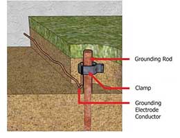
2. Prospecting for good (low resistance) "ground" locations, or obtaining measured resistance values that can give specific information about what lies some distance below the earth's surface (such as depth to bed rock).4 The first (and most important) task to undertake is the actual measurement of resistance to ground at the service entrance meter's electrical ground, or of the soil itself. Several things can affect the actual resistance of the soil, including moisture content, quality and type of electrolytes, conductive objects, temperature, depth and spacing of the ground rods. This critical measurement can be accomplished in one of two ways: either by the use of a special "clamp-on" ground resistance measuring device (good for existing locations) or an earth resistance meter ("Megger") (preferred in new installations). Although the earth resistance meter is less expensive, it requires the use of multiple ground probes and leads from the tester with specific distance requirements between rods and measurements to be plotted on a nomograph in order to calculate the actual resistance of the ground.5
Articles 100 and 250 of the NATIONAL ELECTRIC CODE (NEC) describe an acceptable ground as being rated at 25 Ohms of resistance or less, and requirements to achieve this.5 When the soil resistivity of an area is so high that a low resistance ground isn't feasible, bonding and other requirements, such as transient voltage surge suppression (TVSS) equipment can be implemented to achieve good performance.
A functional earth connection serves a purpose other than shock protection, and may normally carry current. The most important example of a functional earth is the neutral in an electrical supply system. It is a current-carrying conductor connected to earth, often, but not always, at only one point to avoid flow of currents through the earth. The NEC calls it a groundED supply conductor to distinguish it from the equipment groundING conductor. Examples of devices that use functional earth connections include surge suppressors and electromagnetic interference filters, certain antennas and measurement instruments.2
Locations where sound quality is critical, like recording studios, use a "technical ground" to prevent ground loops. Basically, it is a ground where no other appliances are connected to it other than the audio equipment. Even the racks that hold equipment are joined by copper wire or busbars and connected to the ground. These are all connected by the shortest path to a grounding rod that may consist of a heavy copper pipe.
In an electrical substation a ground (earth) mat is a mesh of conductive material installed at places where a person would stand to operate a switch or other apparatus; it is bonded to the local supporting metal structure and to the handle of the switchgear, so that the operator will not be exposed to a high differential voltage due to a fault in the substation.2
Connections to ground limit the build-up of static electricity when handling flammable products or electrostatic-sensitive devices. They allow ESD to flow across their surface but in at a slower rate than a normal conductor. This slower neutralization of ESD prevents damage to microcircuit devices which cannot tolerate a sudden flow of static charge from the device to a grounded mat. Ungrounded conductive or anti-static mats will retain an ESD and transfer the charge to the next object it comes in contact with.3
1. http://en.wikipedia.org/wiki/Earthing_system
2. http://en.wikipedia.org/wiki/Ground_%28electricity%29
3. http://www.anti-staticmat.com/ESDEducation.htm
4. www.meggar.com. gettingdowntoearth.pdf.
5. www.ditekcorp.com/Docs/WhitePapers/Grounding%20101.pdf |