R65 Series
Programmable, DPDT, 10 Amp, AC or DC, Multifunctional, Digital Time Delay Relay/Counter
 |
Features
10 programmable timing modes + 2 counting modes
0.1 sec. to 9,990 hr. programmable timing range
1 to 99,990 counting range
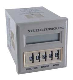
LCD digital display
Thumbwheel switches for programming
|

Electrical Characteristics
Contact
Contact Rating: 10 Amps @ 30VDC or 277VAC, resistive;
1/2 HP @ 250VAC; 1/3 HP @ 120VAC
Life: 100,000 operations at minimum rated load
Mechanical Life: 10,000,000 operations
Input
Nominal Input Voltage: 24 - 240V ±15%, 50/60Hz AC or DC
Nominal Power: See Chart
Timing
Timing Ranges: 0.1 to 99.9/1 to 999 sec.;
0.1 to 99.9/1 to 999 min.; 0.1 to 99.9/1 to 999/10 to 9,990 hr.
Timing Adjustments: Digital adjustments via thumbwheel switches
Tolerance: ±0.1% ±0.05 sec.
Delta Time (for AC units add ±1 cycle 60Hz): ±0.1% ±0.05 sec.
Repeatability: ±0.1% ±0.05 sec. - including first cycle of operation
Reset Time (power interruption): 45mS Typ.; 60mS Max.
Minimum Pulse Width, Control: 50mS
Recycle Time: 45mS Typ.; 60mS Max.
Counting
Maximum Count: 1 to 999; 10 to 9,990 (÷10);
100 to 99,900 (÷100)
Maximum Count Rate: 100 counts per second
Minimum Pulse Width:
Count (Control): 3mS
Reset: 3mS
Available Counting Functions: Operate at preset count and release at preset count
Protection
Transient: Yes
Dielectric Strength:
Between Open Contacts: 1000Vrms, 60Hz
Between All Other Conductors: 1500Vrms, 60Hz
Environmental Characteristics
Operating: -10°C to +55°C
Storage: -20°C to +70°C
Weight
Std: 4.3ozs. (122g) approx.
Back to Top
Dimensional Drawings
D36
Contact Arrangment
DPDT, 2 Form "C"
 |
Back to Top
Part Numbers
| AC or DC OPERATED |
NTE
Type No. |
Timing
Adj
Range |
Count
Range |
Contact
Arr. |
Nom Vltg AC/DC |
Nom
Power |
Max.
Contact
Cur.
@
28VDC
120VAC |
| R65-11AD10 |
0.1sec.
to
9,990hr. |
1
to
99,900 |
DPDT |
24
to
240 |
1W@24V
5W@120V
10W@240V |
10A |
| ACCESSORIES |
| Mounting Styles |
Description |
NTE Type No. |
| Surface Mount |
11-Pin Octal |
R95-104 |
| Panel Mount |
11-Pin Octal |
R95-119 |
| DIN Rail
Mount |
11-Pin Octal |
R95-114 |
| 11-Pin Octal |
R95-182 |
Back to Top
Timer Function Descriptions
A. Delay On Operate
Output relay
turned on at end of programmed time interval which is started by CONTROL
input or power-on with CONTROL on. Relay turned off by RESET input until
next cycle is started. With CONTROL on, turning RESET off restarts
timing.
B. Delay On Release
Output relay turned on with
CONTROL input and remains on for programmed time interval following
removal of CONTROL. During time interval after release of CONTROL, RESET
turns relay off until cycle restarted with reapplication of CONTROL. With
CONTROL on, relay is held off while RESET is activated.
C. Interval On
Output relay turned on for
programmed time interval by CONTROL or power-on with CONTROL on. RESET
turns relay off until next cycle is started, and does not restart timing
when RESET is removed.
D. Control-Off Interval On
Output relay turned
on for programmed time interval by turn-off of CONTROL. RESET turns relay
off until next cycle is started, and does not restart timing when RESET is
removed.
E. Recycle
Output relay turned on at end of
programmed time interval which is started by momentary CONTROL input or
power-on with CONTROL on. Relay stays on for equal time interval, then
turns off and cycle is repeated on a free-running basis until terminated
by momentary RESET, turning relay off. With CONTROL on, turning RESET off
restarts cycle.
F. Single Cycle
Output relay turned on at end
of programmed time interval which is started by momentary CONTROL input
or
|
power-on with CONTROL on. Relay stays on for equal time
interval, then turns off. RESET terminates timing and turns relay off.
Turning RESET off does not restart timing.
G. Control On-Off Interval On
(Watch Dog Timer)
Output relay turned on and programmed time interval started of
restarted by change of CONTROL input. RESET turns relay off and stops
timing. Turning RESET off does not restart timing.
H. Control On-Off Delay
Output relay turned on
at end of programmed timing interval which is started or restarted by
change of CONTROL input. If relay is on, turn-off of relay occurs at end
of programmed time interval which is started or restarted by change of
CONTROL input. RESET turns relay off and stops timing. Turning RESET off
does not restart timing.
I. Pulse
Output relay turned on at end of
programmed time interval, which is started by CONTROL input, for 0.5
second duration, and continuesin pulsed mode at programmed time interval
with fixed 0.5 second on-time. Turning CONTROL off turns relay off and
stops timing. RESET turns relay off and inhibits operation. With CONTROL
on, removal of RESET restarts timing.
J. Cumulative Delay On Operate
Output relay
turned on at completion of total accumulate CONTROL input duration equal
to programming time. Turning CONTROL off before accumulation of programmed
time results in measured time total being held until CONTROL is again
turned on and total programmed time value is reached. RESET input resets
time value to zero and turns relay off if energized. Turning RESET off
restarts timing if CONTROL is on. |
Counter Function Descriptions
CO. Operate at Preset Count - Normal Mode
After initializing by momentary activation of RESET input, each
on/off signal at COUNT (CONTROL) input increments displayed count in
upcounting manner from initial 000 value until preset count, set by
thumbwheel switches, is reached and output relay turns on. Additional
inputs continue to increment displayed count. Continued counting past
maximum count (999) results in a "wrap-around" effect to 000, followed by
continued up-counting. Activation of RESET input turns relay off and
resets count to zero.
CR. Release at Preset Count - Normal Mode
Initializing by momentary activation of RESET input
turns |
relay on. Operation is similar to CO (Operate at Preset
Count) except relay turns off at preset count.
CO or CR. Divide-by-10 Mode
Operation is as
described previously, except count is incremented for every 10 on/off
input signals for a maximum presettable count of 9,990.
CO or CR. Divide-by-100 Mode
Operation is as
described previously, except count is incremented for every 100 on/off
input signals for a maximum presettable count of
99,900. |
Back to Top
|